
Defect Prevention Starts Long Before The First Casting Is Produced
Casting remains one of the most efficient and versatile manufacturing processes available to engineers. Modern high pressure die casting and gravity die casting techniques can produce highly complex components with excellent dimensional accuracy, repeatability and mechanical performance. However, achieving consistently high-quality castings is not simply a matter of pouring molten metal into a mould and waiting for it to solidify.
In every casting process there is a risk that defects may form. Some are immediately visible. Others remain hidden beneath the surface until machining, testing or even service conditions reveal them. In critical applications, a seemingly minor defect can compromise mechanical properties, reduce fatigue life, create leakage paths or result in costly scrap and rework.
The reality is that defect-free castings are rarely the product of chance. They are the result of careful component design, appropriate process selection, robust tooling, disciplined process control and decades of engineering experience.
Get expert technical advice on defect-free casting
Why Casting Defects Occur
At its core, casting involves transforming liquid metal into a solid component. During that transformation, the metal is subjected to significant thermal, mechanical and metallurgical changes, such as:
- Grain formation and growth – as the alloy solidifies, crystals nucleate and grow to form the grain structure of the casting. Grain size and morphology have a significant influence on strength, ductility and fatigue performance.
- Segregation of alloying elements – silicon, copper, magnesium and other elements can redistribute during solidification, creating local variations in composition that affect mechanical properties, machinability and corrosion resistance.
- Formation of intermetallic phases – alloying elements combine to form intermetallic compounds within the microstructure. Depending on their type and distribution, these phases can either enhance performance or reduce ductility.
- Hydrogen rejection and porosity formation – hydrogen is far more soluble in liquid aluminium than it is in solid aluminium. As the metal solidifies, dissolved hydrogen is expelled and can create gas porosity if it cannot escape.
- Development of residual stresses – different sections of the casting cool and contract at different rates, generating internal stresses that can lead to distortion, dimensional instability or cracking.
- Microstructure development – the cooling rate determines the final microstructure of the casting. This influences hardness, strength, wear resistance and suitability for subsequent heat treatment.
- Precipitation hardening potential (age hardening) – in heat-treatable alloys, the as-cast microstructure affects how the material will respond to later heat treatment processes and the mechanical properties that can ultimately be achieved.
The molten alloy must flow efficiently through the die or mould, fill every section of the cavity, release trapped gases, solidify in a controlled manner and cool without introducing excessive stresses.
Whenever one of those stages is not properly controlled, defects can develop.
The challenge is compounded by the fact that many defects have multiple contributing factors. A porosity issue may be caused by die design, melt quality, process parameters or component geometry. Effective defect prevention therefore requires a holistic understanding of the entire manufacturing process.
Contact us for advice on defect-free casting
Gas Porosity: The Hidden Enemy
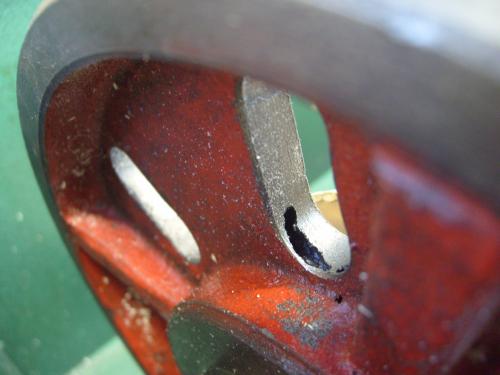
Gas porosity is one of the most common defects encountered in aluminium die castings – particularly in high pressure die casting. It occurs when gas becomes trapped within the casting and is unable to escape before the metal solidifies. The defect appears as small spherical voids trapped within the casting structure.
In high pressure die casting, the rapid injection speeds required to fill complex geometries can create turbulence within the metal stream. This turbulence can trap air within the casting. Hydrogen absorption within aluminium melts can also contribute to gas porosity if melt treatment is not properly controlled.
The consequences can be significant. Internal porosity reduces mechanical strength, compromises pressure tightness and can create problems during machining. Components can be particularly vulnerable when intended for welding, surface finishing or impregnation (a specialist sealing process used to eliminate microscopic leak paths caused by fine porosity).
Prevention of gas porosity begins with optimised gating and runner design to minimise turbulence. Effective venting systems allow displaced air to escape from the cavity. Vacuum-assisted die casting can further reduce gas entrapment. Careful melt treatment and degassing procedures are equally important in maintaining metal quality before casting begins.
Shrinkage Porosity: A Solidification Challenge
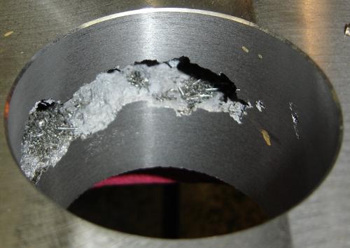
Unlike gas porosity, shrinkage porosity occurs during solidification. As molten metal cools, its volume decreases. If sufficient liquid metal is not available to feed areas that are solidifying, voids can form within the casting structure.
Open shrinkage results in cavities that are exposed to the surface of the casting. These occur when the final area to solidify is located at or near the casting surface and the contracting metal pulls away, leaving a visible depression, pipe or cavity. Open shrinkage is often relatively easy to identify during visual inspection because it appears as a sink, crater or void on the casting surface.
Closed shrinkage leads to porosity or cavities that are completely enclosed within the casting. The external surface may appear perfectly sound, while internal voids remain hidden beneath. Closed shrinkage can be detected only through non-destructive testing methods such as X-ray inspection, CT scanning or ultrasonic testing, or by destructive sectioning of the casting.
Shrinkage defects are more commonly associated with gravity die casting than with high pressure die casting, although they can occur in both processes.
These defects often develop in thicker sections where solidification occurs more slowly. Poor section transitions and inadequate feeding systems can exacerbate the problem.
The resulting voids are often irregular in shape and can significantly reduce structural integrity. They may also become exposed during machining operations, resulting in component rejection.
Shrinkage porosity is generally divided into two main types:
- Macroshrinkage (or shrinkage cavities) – large concentrated voids that form when there is insufficient liquid metal available to feed a section as it solidifies. These defects are usually visible on sectioned castings or radiographs and often occur in heavy sections, bosses or areas where solidification has become isolated from the feeding source. Macroshrinkage typically appears as a single large cavity or a cluster of interconnected voids. Inadequate feeding during solidification is often the cause.
- Microshrinkage (or interdendritic shrinkage) – fine dispersed voids that form between the dendrites (the tree-like crystals that develop during solidification). These pores are much smaller than macroshrinkage cavities and are often distributed throughout a localised region of the casting. While they may not be visible to the naked eye, they can reduce mechanical properties, pressure tightness and fatigue performance. Microshrinkage is usually caused by localised feeding deficiencies within the final stages of solidification.
Preventing shrinkage porosity requires careful control of solidification patterns. Engineers use simulation software, directional solidification principles, feeders and optimised wall thicknesses to ensure metal continues feeding critical areas until solidification is complete. Another option is to use chills – highly conductive metal inserts placed within a mould or die to increase the local cooling rate of the molten metal during solidification.
Contact us for more advice on preventing shrinkage
COLD SHUTS: When Metal Fails to Fuse
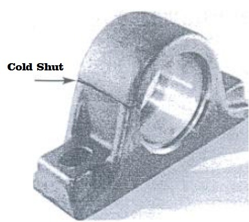
A cold shut occurs when two separate streams of molten metal meet but fail to fuse completely.
The defect typically appears as a visible line or seam on the casting surface and can create a significant weakness within the component.
Cold shuts are usually caused by insufficient metal temperature, slow filling rates or excessively long flow paths. Thin-walled sections and complex geometries are highly susceptible.
In high pressure die casting, cold shuts can occur if injection parameters are not properly optimised. In gravity die casting, insufficient mould temperatures or poor gating arrangements may be responsible.
The impact extends beyond appearance. Cold shuts create stress concentration points that can reduce fatigue performance and increase the risk of cracking under load.
Experienced foundry engineers address the issue through careful gating design, thermal analysis and process optimisation to ensure metal fronts meet under the correct conditions for complete fusion.
Misruns: Incomplete Filling of the Casting
Closely related to cold shuts is the misrun. This occurs when molten metal solidifies before the mould cavity is completely filled. The resulting casting is incomplete and unusable.
This defect is particularly common in thin sections, intricate geometries and components with long flow lengths.
Insufficient pouring temperature, inadequate mould temperature and poor gating design are among the most common causes.
Modern casting simulation software has become an invaluable tool in identifying potential misrun risks before tooling is manufactured. Combined with robust process development, this significantly improves first-time-right production outcomes.
Oxide Inclusions: The Defect You Can’t Always See
Aluminium alloys naturally form oxide films when exposed to air. Under controlled conditions, these films present little concern. However, excessive turbulence during metal handling or mould filling can fold oxide films into the casting structure.
These oxide inclusions create discontinuities within the metal matrix and can severely reduce mechanical properties.
Unlike many other defects, inclusions may not always be visible externally. They often require radiography, metallographic examination or destructive testing to identify.
Controlling oxide formation requires disciplined melt handling procedures, carefully designed gating systems and minimisation of unnecessary turbulence throughout the casting process.
Get expert technical advice on defect-free casting
Hot Tearing and Solidification Cracking
Hot tearing occurs when a casting experiences tensile stresses during the final stages of solidification.
As the metal contracts, areas of the casting may become restrained by geometry or tooling features. If the metal lacks sufficient strength at that moment, cracks can develop.
Complex geometries, abrupt section changes and certain alloy compositions are particularly susceptible – notably alloys that solidify over a wide temperature range, including many aluminium-copper and aluminium-magnesium casting alloys.
Hot tearing defects are especially problematic because they can compromise structural integrity and often prove difficult to repair economically.
Prevention depends heavily on casting design. Uniform wall sections, generous radii and controlled solidification patterns all contribute to reducing the risk.
Surface Defects and Appearance Issues
Not all defects affect structural performance directly but surface quality remains critically important.
Surface defects can include:
-
Blistering – raised bubbles or swellings that appear on the casting surface when trapped gases expand during subsequent heating operations such as heat treatment, powder coating or machining. Blistering is most commonly associated with high pressure die castings containing entrapped air porosity. Although often viewed as a surface defect, blistering can indicate significant internal gas content and may render the component unsuitable for finishing processes.
-
Flow marks – visible streaks, lines or ripples on the casting surface caused by variations in metal flow during cavity filling. Flow marks typically occur when the molten metal cools unevenly as it advances through the die, creating visible boundaries between metal streams at different temperatures. While usually cosmetic, these marks can be indicative of suboptimal gating design, die temperature control or filling parameters.
-
Laps – surface folds formed when a stream of molten metal folds back on itself and partially solidifies before fusing fully with the underlying metal. Laps often contain oxide films trapped within the fold, creating localised weaknesses and potential crack initiation sites. They are typically caused by turbulent flow, poor gating design or incorrect filling velocities.
-
Die soldering – a defect in which molten aluminium partially adheres to the die surface during casting. This occurs when local die temperatures become excessive or when alloy chemistry promotes interaction between the molten metal and the tool steel. Soldering can damage the die surface, impair dimensional accuracy, increase maintenance requirements and create rough areas on the casting surface.
-
Erosion marks – surface defects caused by molten metal progressively wearing away the die surface, particularly in areas exposed to high-velocity metal flow. Over time, this erosion alters cavity geometry, degrades surface finish and can affect dimensional consistency. Erosion is often concentrated around gates, runners and sharp directional changes in the metal flow path.
-
Roughness variations – localised differences in surface texture across the casting, ranging from smooth areas to regions with a coarse or grainy appearance. These variations can arise from inconsistent die temperatures, uneven die lubrication, poor venting, die wear or fluctuations in process parameters. Though mainly a matter of appearance and feel, roughness variations can also affect coating adhesion and downstream machining operations.
While some surface defects are primarily cosmetic (and still to be prevented), others can indicate underlying process issues.
In sectors such as medical equipment, electronics housings and premium consumer products, the requirements can be extremely demanding – calling for the highest quality surface finishing.
Achieving consistent surface finish requires stable process parameters, carefully maintained tooling, effective lubrication and rigorous thermal management of the die.
Get expert technical advice on defect-free casting
Flash and Dimensional Instability
Flash occurs when molten metal escapes between mating surfaces of the die.
While often considered a relatively minor defect, excessive flash can indicate tooling wear, machine alignment issues or excessive injection pressures.
Dimensional instability can arise from inconsistent process conditions, thermal distortion or inadequate control of solidification behaviour.
For precision-engineered components, even small dimensional variations can create assembly problems, increase machining costs or result in component rejection.
Maintaining tight dimensional tolerances requires not only accurate tooling but also disciplined process control throughout the production lifecycle.
Why Process Selection Matters
Not every casting process presents the same risks.
High pressure die casting is excellent for the production of complex, high-volume components with excellent dimensional consistency and surface finish. However, the rapid filling process can increase susceptibility to gas-related defects if tooling and process parameters are not properly engineered.
Gravity die casting generally produces lower levels of gas entrapment and can deliver excellent mechanical properties. However, because filling occurs more slowly, greater attention must be paid to feeding behaviour and shrinkage control during solidification.
The most appropriate process depends on the component geometry, performance requirements, production volume and downstream manufacturing operations.
Selecting the correct process at the beginning of a project often prevents quality issues long before production begins.
Interconnected Defects
Many defects can be linked:
-
A poorly designed boss can create a hot spot – leading to shrinkage porosity.
-
An attempt to eliminate shrinkage by increasing injection speed can increase air entrapment and gas porosity.
-
A die temperature change intended to improve filling can increase die soldering.
-
A gating modification that reduces turbulence can also reduce oxide inclusions and laps simultaneously.
This is why experienced foundry engineers rarely look at a defect in isolation. The real skill lies in understanding the interaction between alloy selection, component geometry, gating/runner design, venting, die temperature management, melt quality, process parameters, and downstream machining and finishing requirements.
The most effective way to eliminate casting defects is not merely through inspection but through prevention. A well-designed casting combines the right alloy, the right process, intelligent tooling design and tightly controlled manufacturing parameters.
Designing In Quality From The Start
The most successful casting projects are those in which quality is designed into the component at the earliest possible stage.
Foundry engineers, design engineers and manufacturing teams achieve the best results when they collaborate before tooling is commissioned. Wall thicknesses can be optimised, feeding paths improved, thermal behaviour understood and potential defect risks eliminated before they become potentially expensive production challenges.
Modern simulation tools, advanced process monitoring and sophisticated inspection technologies all play important roles. However, they are most effective when combined with practical engineering knowledge developed through decades of specialist die casting experience.
Get Expert Technical Help
Defect-free castings do not happen by accident. Every successful component reflects a myriad of engineering decisions involving design, alloy selection, tooling, melt treatment, process control and inspection.
Whether the challenge is preventing gas porosity in high pressure die casting, controlling shrinkage in gravity die casting or eliminating cold shuts in a complex geometry, the underlying principle remains the same: understand the mechanism, control the process and remove the root cause before the defect has an opportunity to form.
That approach is what separates a casting supplier from a true manufacturing partner. The goal is not simply to detect defects after production. It is to engineer them out of the process altogether.